10 Best Inductors for Electronics Sourcing in 2026?

Choosing the right inductor can decide whether an electronic design runs quietly or fails under load. In 2026, sourcing teams face tighter efficiency targets, faster product cycles, and unstable component availability. This guide, “10 Best Inductors for Electronics Sourcing in 2026,” examines practical options for power supplies, automotive modules, industrial controls, and compact consumer devices.

Real-world selection requires more than comparing inductance values. Engineers should check saturation current, rated current, DC resistance, self-resonant frequency, temperature rise, and tolerance. A compact 4.7 µH part may fit the board beautifully. However, it can overheat beside a switching regulator. Datasheets matter. Testing matters more.

As EMC engineer Henry Ott advised, “The best way to solve a problem is to avoid it.” That principle applies directly to inductors electronics sourcing. Early screening can prevent magnetic noise, unexpected voltage ripple, and costly redesigns. Reliable suppliers should provide traceable documentation, consistent samples, and clear lifecycle information. Qualification evidence is essential.

This list is not perfectly universal. A strong inductor for one circuit may be unsuitable for another. That limitation deserves attention. Package height, airflow, core material, and switching frequency can change the final decision. We compare each candidate through an engineering and procurement lens, balancing electrical performance, availability, price, and long-term reliability. Some rankings may still shift as manufacturers update production lines. That is the uncomfortable reality of sourcing.
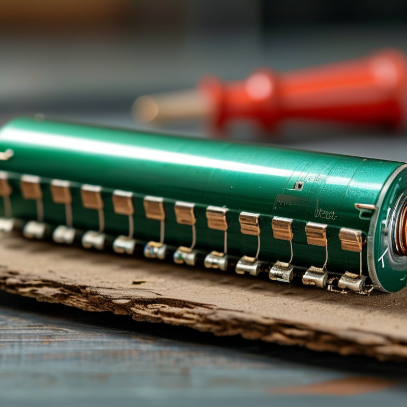
10 Best Inductors for Electronics Sourcing in 2026?

Inductor Fundamentals and Their Role in Modern Electronics

10 Best Inductors for Electronics Sourcing in 2026?

Inductors store energy in magnetic fields and resist rapid current changes. Their value is measured in henries, while impedance rises with frequency. Designers must also check saturation current, DC resistance, quality factor, and self-resonant frequency. These figures define performance more accurately than inductance alone.

Power inductors often use ferrite or powdered cores. Multilayer types suit compact signal circuits. Shielded constructions can reduce magnetic interference near sensors and wireless modules.

WSTS forecasts global semiconductor sales will reach about 772 billion dollars in 2026. That growth increases demand for stable power conversion and efficient filtering. MarketsandMarkets projects the inductor market to grow from roughly 4.3 billion dollars in 2023 to 6.1 billion dollars by 2028.

Small details matter.

During sourcing, I compare the rated current with real ripple current, not just the datasheet headline. Thermal rise also deserves attention. A component may pass its electrical test and still run too hot inside a sealed enclosure. This is where selection becomes less tidy. Reported values often use different test frequencies, temperatures, or tolerance limits. Engineers should verify conditions under IEC-based testing and request equivalent curves from suppliers. Footprint, height, mounting stress, and availability over the product lifecycle can change the best choice. A low-cost inductor is not automatically economical when noise, rework, or field failures appear later.

Key Specifications for Comparing Inductors in 2026

When comparing inductors in 2026, inductance is only the starting point. The specified value must match the converter’s switching frequency and control loop. Tolerance matters too, especially when a filter leaves little design margin. I measure the part at its actual operating frequency, not only at 100 kHz. Small details matter.

Saturation current shows when inductance drops under load, while rated current usually reflects heating limits. Do not treat them as interchangeable. Check DC resistance because a few extra milliohms can raise losses in a high-current rail. For filtering, review Q factor, self-resonant frequency, impedance curves, and attenuation across the target band. Shielded construction can reduce magnetic coupling, but it may increase cost or size. The trade-off is real.

Package height, pad layout, thermal path, and mechanical strength affect production yield. I also compare temperature drift, storage conditions, moisture sensitivity, and declared test methods. A datasheet without test conditions is incomplete evidence. Request samples and inspect winding quality, solderability, acoustic noise, and temperature rise on the intended PCB. One selection failed my first review because its current rating assumed a cooler ambient. That mistake was avoidable. Check lifecycle data, lot traceability, and second-source compatibility before approving volume orders.

Ten Leading Inductor Types for Electronics Sourcing

In 2026, electronics sourcing teams need more than a low unit price. The ten leading inductor types include power inductors, multilayer ceramic inductors, wirewound inductors, shielded inductors, molded inductors, ferrite beads, common-mode chokes, RF inductors, coupled inductors, and variable inductors. Each type serves a different electrical purpose. Power inductors handle energy storage in converters, while ferrite beads suppress high-frequency noise on compact circuit boards. Small parts, serious consequences.

Wirewound and molded designs often provide stable current performance, but their size and heat behavior require careful review. Shielded inductors can reduce magnetic interference near sensors, clocks, and communication circuits. Multilayer ceramic types suit high-frequency applications with limited space. RF and variable inductors support tuning networks, antenna matching, and signal filtering. Coupled inductors can simplify isolated or multi-output power sections. Common-mode chokes target unwanted noise on paired conductors.

Experienced buyers should compare inductance tolerance, saturation current, rated temperature, DC resistance, impedance curves, and mechanical dimensions. Ask for recent test reports and production samples. Verify performance at the actual switching frequency, not only at the headline specification. I once approved a compact part that passed bench testing but overheated inside a sealed enclosure. That mistake still influences my sourcing checklist. Datasheets can be accurate, yet incomplete without thermal and layout context. Reliable suppliers should explain changes in materials, winding processes, inspection methods, and lot traceability before volume purchasing begins.

10 Best Inductors for Electronics Sourcing in 2026? - Ten Leading Inductor Types for Electronics Sourcing

A practical comparison of widely used inductor types for power conversion, filtering, signal processing, electromagnetic compatibility, and energy-storage applications.

Rank Inductor Type Typical Inductance Range Typical Current Capability Common Operating Frequency Key Advantages Main Limitations Typical Applications Important Sourcing Criteria
1 Shielded Power Inductor 0.1 µH–1 mH 0.5–100 A 20 kHz–5 MHz Low magnetic leakage, strong EMI performance, compact surface-mount packages, and good suitability for high-current DC-DC converters. Usually more expensive than unshielded designs; saturation and temperature rise must be checked at the actual operating current. Voltage regulators, point-of-load converters, battery-powered equipment, automotive power modules, and FPGA power supplies. Compare saturation current, rated current, DC resistance, thermal derating, package height, shielding structure, and pad compatibility.
2 Unshielded Drum-Core Inductor 1 µH–100 mH 0.1–20 A 10 kHz–1 MHz Cost-effective construction, broad availability, high inductance options, and simple design integration. Greater magnetic flux leakage can increase electromagnetic interference and coupling with nearby circuits. General-purpose power supplies, LED drivers, filters, control equipment, and low-cost consumer electronics. Check mechanical clearance, open magnetic field, inductance tolerance, audible-noise behavior, lead or terminal style, and insulation requirements.
3 Multilayer Ceramic Chip Inductor 0.6 nH–470 nH 10 mA–1 A 10 MHz–10 GHz+ Very small size, low parasitic capacitance, high self-resonant frequency, and excellent suitability for RF circuits. Limited current handling and relatively low inductance compared with power inductors; electrical performance is sensitive to layout and frequency. RF matching networks, impedance tuning, wireless communication, antennas, filters, and high-frequency signal paths. Evaluate Q factor, self-resonant frequency, tolerance, temperature coefficient, size code, mounting orientation, and RF test conditions.
4 Wirewound RF Inductor 10 nH–10 µH 20 mA–3 A 1 MHz–3 GHz High Q factor, stable RF characteristics, and better current handling than many multilayer ceramic inductors. Generally larger and more costly; parasitic capacitance and winding geometry affect high-frequency behavior. RF front ends, oscillators, filters, impedance matching, radio modules, and high-frequency power conditioning. Request Q-versus-frequency data, self-resonant frequency, current rating, tolerance, shielding option, and approved land pattern.
5 Toroidal Inductor 1 µH–100 mH 0.2–50 A 50 Hz–500 kHz Efficient magnetic path, low external flux leakage, good energy storage, and strong performance in differential-mode filtering. Winding and termination can increase assembly cost; larger cores may require manual or specialized production processes. Power filters, audio equipment, inverters, renewable-energy systems, industrial controls, and energy-storage circuits. Confirm core material, winding fill, insulation system, temperature rise, mechanical mounting, creepage distance, and production method.
6 Common-Mode Choke 10 µH–100 mH 0.1–30 A per winding 50 kHz–300 MHz Suppresses common-mode noise while allowing intended differential current to pass; available in through-hole and surface-mount formats. Performance depends heavily on source impedance, winding balance, leakage inductance, and installation layout. AC input filters, USB and data interfaces, Ethernet, automotive networks, motor drives, and switching power supplies. Check common-mode impedance, differential-mode insertion loss, rated current, insulation voltage, hipot performance, winding balance, and safety approvals.
7 Ferrite Bead Impedance-based: typically 10–2,000 Ω at a specified test frequency 0.1–10 A 1 MHz–1 GHz+ Simple EMI suppression, low cost, small footprint, and effective attenuation of high-frequency noise on power and signal lines. Not a conventional energy-storage inductor; impedance varies with frequency, DC bias, temperature, and installed circuit conditions. Power-rail noise suppression, processor supply filtering, display interfaces, sensor lines, and high-speed digital electronics. Use impedance curves rather than a single nominal value; verify DC resistance, rated current, DC-bias behavior, temperature rise, and signal integrity.
8 Power Transformer-Style Coupled Inductor 1 µH–10 mH per winding 0.5–50 A 20 kHz–2 MHz Supports coupled energy transfer, ripple cancellation, multi-output conversion, and reduced magnetic-component count in some topologies. Requires careful winding polarity, coupling, insulation, leakage-inductance, and thermal design; replacement parts are less interchangeable. SEPIC converters, coupled-buck circuits, multi-phase converters, active filters, and isolated or semi-isolated power architectures. Specify coupling coefficient, turns ratio, leakage inductance, insulation system, winding sequence, saturation current, and creepage and clearance.
9 Molded Composite Power Inductor 0.1 µH–100 µH 1–150 A 100 kHz–5 MHz Low acoustic noise, robust mechanical construction, compact high-current packages, and reduced magnetic radiation from the molded core. Thermal performance can be limited by the small package; inductance may change significantly under DC bias. Automotive electronics, processors, graphics systems, industrial power modules, telecommunications, and high-density computing equipment. Compare soft-saturation behavior, DC-bias curves, DCR, core loss, thermal impedance, vibration performance, and automated assembly compatibility.
10 Axial Leaded Inductor 1 µH–100 mH 20 mA–5 A 1 kHz–1 MHz Convenient for through-hole assembly, simple visual inspection, flexible lead placement, and easy replacement in legacy designs. Larger board area than many surface-mount parts; lead length can add parasitic effects and reduce high-frequency performance. Audio crossovers, legacy control boards, power filters, repair markets, educational equipment, and low-to-medium frequency circuits. Verify lead spacing, body dimensions, inductance tolerance, rated current, DCR, insulation coating, mounting orientation, and long-term availability.

Note: The electrical ranges shown are representative sourcing guidelines, not universal limits. Final selection should be based on the manufacturer’s datasheet, operating frequency, DC bias, core temperature, saturation definition, tolerance, safety requirements, and the complete circuit layout.

How to Match Inductors with Circuit and Application Requirements

Selecting an inductor starts with the circuit, not the catalog ranking. For a buck converter, calculate inductance from switching frequency, input voltage, output voltage, and permitted ripple current. A practical target is often 20–40% of the maximum load current. Then check saturation current at the real operating temperature. A part rated at 25°C may lose meaningful margin inside a compact, warm enclosure.

DC resistance matters too. Lower resistance reduces copper loss, but it can increase size, cost, and parasitic capacitance. For high-frequency designs, inspect the self-resonant frequency and impedance curve, not only the nominal microhenry value. MarketsandMarkets’ Inductor Market report projects growth from approximately USD 4.7 billion in 2024 to USD 6.2 billion by 2029, driven partly by power electronics and connected devices. That growth increases sourcing choices, but also creates more datasheet comparisons.

Tips: Build a requirement table before requesting quotations. Include inductance tolerance, RMS current, saturation current, DCR, temperature rise, package height, and qualification data. Request test conditions for every current rating. Do not compare values blindly. A 10 µH inductor with a 2 A rating may behave poorly at 100°C. I have seen otherwise suitable designs fail because engineers checked nominal inductance only. Recheck ripple, thermal rise, and acoustic behavior on the assembled PCB. Industry guidance helps, but the final measurement remains the most reliable evidence.

Supplier Evaluation, Quality Control, and Procurement Considerations

For the 10 best inductors in 2026, supplier evaluation should begin with application fit, not price. WSTS forecasts global semiconductor sales will reach $749.7 billion in 2026. That growth may intensify demand for dependable passive components. Compare inductance tolerance, DC resistance, saturation current, shielding, thermal rise, and operating temperature. A cheaper part can become expensive after field failures.

Quality control needs evidence. Request control plans, material declarations, lot traceability, and test records for every shipment. Check impedance and inductance at defined frequencies, not only at room temperature. For automotive or industrial use, review process audits, change-notification procedures, and corrective-action history. The IEC 60068 test framework can support vibration, humidity, and temperature testing. However, laboratory results do not always represent a crowded production line.

Procurement teams should examine lead-time history, minimum order quantities, capacity allocation, tooling ownership, and authorized second sources. Mordor Intelligence estimates the power inductor market will expand at roughly 6% annually through the decade, increasing supply pressure. Use total landed cost instead of unit price alone. I have seen technically excellent samples fail during ramp-up because packaging caused moisture damage. That mistake is easy to repeat. A supplier scorecard should reserve measurable weight for delivery stability, communication speed, and traceable quality records. Keep a production sample from each approved lot. It is simple, but often forgotten.

10 Best Inductors for Electronics Sourcing in 2026

The chart uses ten nominal inductance values from the IEC E12 preferred-value series as a neutral sourcing reference. These values are not a performance ranking; final supplier evaluation should also verify tolerance, saturation current, RMS current, DC resistance, operating temperature, package size, qualification records, and quality-control documentation.