How to Choose the Right Impressed Current Anode?
Choosing an Impressed Current Anode is a design decision, not a product-size guess. The right system must deliver protective current across the structure without creating avoidable maintenance or power demands. The NACE IMPACT study, published in 2016, estimated that corrosion costs the global economy US$2.5 trillion annually, or 3.4% of global GDP. It also reported that applying existing corrosion-control practices could save 15–35% of those costs. These figures show why protection deserves careful engineering. They do not, however, tell you which anode to buy.
Start with the structure and its operating environment. Record the electrolyte’s resistivity, temperature, and chemistry, then assess coating condition, exposed surface area, and current demand. A buried pipeline, a seawater tank, and a reinforced concrete structure require different anode arrangements. Check anode material, rated output, expected consumption, cable connections, and compatibility with the rectifier and monitoring system. Design calculations should also consider current distribution, interference risks, access for inspection, and the intended service life. Details matter.
Standards and field measurements help turn those inputs into a defensible specification. Obtain site-specific data where possible; assumptions about soil or water can quietly skew the design. Ask suppliers for documented performance data and a clear basis for their service-life estimates. Then have a qualified corrosion professional review the design against applicable industry standards. A tempting shortcut is selecting the highest-output unit. That can be the wrong answer. The best choice balances reliable protection, practical installation, and maintainable operation—not a single headline rating.
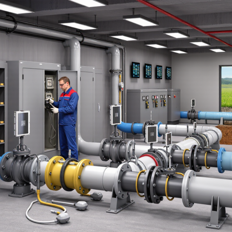
Define the Protection Requirements and Operating Environment
Before selecting an impressed current anode, define what the structure must be protected against. Record its material, dimensions, coating condition, and exposed surface area. A steel tank with damaged coating may need more current than a well-coated pipeline of similar size. Small details matter.
Set protection targets using applicable engineering criteria and measurements from the actual site. Consider electrolyte resistivity, temperature, moisture, and changing conditions. Seawater, soil, and process liquids behave differently. Measure, don’t guess. Reference electrode readings and current demand estimates help establish a realistic design basis, but field conditions can still vary.
The operating environment also shapes anode choice and placement. Note available space, liquid flow, deposits, abrasion, and access for inspection or replacement. Uneven geometry can create areas that receive too little current, even when the system’s total output appears adequate. Check for electrical continuity and possible interference from nearby structures. Maintenance access is easy to overlook. It should not be. Document assumptions, then verify them during commissioning and routine surveys. If conditions change, such as coating damage or altered fluid composition, reassess the protection requirements rather than relying on the original settings.
Compare Anode Materials, Shapes, and Installation Options
An impressed current anode should match the required output, environment, and installation space. Mixed-metal-oxide-coated titanium is common where compact, long-lasting anodes are needed. High-silicon cast iron can suit demanding groundbeds, but it is brittle and needs careful handling. Graphite is another option, though its performance depends on the electrolyte and installation conditions. No material wins everywhere.
Shape affects current distribution. Tubular or rod anodes fit deep wells and narrow excavations; ribbon or mesh can spread current across larger structures. Soil resistivity matters. A resistivity survey helps estimate anode-bed performance before crews dig. The NACE International IMPACT study estimated corrosion costs at US$2.5 trillion globally, or 3.4% of world GDP, and reported that better corrosion management could save 15–35% of those costs. That is useful context, not a project-specific forecast.
Installation choices include shallow distributed beds and deep vertical beds. Shallow beds may be easier to inspect, while deep beds can reduce surface disruption and help reach suitable soil layers. For deep installations, conductive backfill and sound cable connections matter; small defects can undermine an otherwise careful design. I would not choose from a catalogue alone. Site conditions change. Even a well-calculated layout can need adjustment after commissioning measurements.
How to Choose the Right Impressed Current Anode?
Typical forms and installation options by anode material
How to read the chart: 1 indicates a commonly used pairing; 0 indicates it is not a typical choice. These are qualitative comparisons, not design limits—project conditions and supplier specifications matter.
Selection guide: MMO-coated titanium is available as tubular, ribbon, and mesh anodes for groundbeds, water, and reinforced-concrete systems. High-silicon cast iron and graphite are commonly used in shallow or deep groundbeds. Platinized titanium or niobium is often selected for compact anodes in water or tank applications. Choose the shape and installation method to suit the electrolyte, required current, structure, and access for maintenance.
Estimate Current Demand and Select a Suitable Power Supply
How to Choose the Right Impressed Current Anode?
Estimate Current Demand and Select a Suitable Power Supply
Start with the steel area that actually needs protection, not the entire structure’s surface area. Divide it into coating zones, then estimate exposed area using coating condition and likely damage. DNV-RP-B401 provides design current-density guidance for offshore structures, with values that vary by seawater conditions and coating breakdown. Use the applicable project conditions; a single generic figure can badly misstate demand. For a preliminary check, 100 m² of exposed steel at 0.1 A/m² requires about 10 A. That is only an estimate. Field measurements and qualified corrosion-engineering review should refine it.
Size the rectifier for the calculated current and the voltage needed to overcome anode-bed, cable, and electrolyte resistance. Under Ohm’s law, voltage must cover the circuit resistance at the target output; extra current capacity cannot compensate for inadequate voltage. Allow practical operating headroom for coating deterioration and changing conditions, while avoiding excessive output that could damage coatings or cause hydrogen-related problems. ISO 15589-2 addresses cathodic protection design for offshore pipelines, including design conditions that affect current demand. Check its scope before applying its criteria elsewhere. Measure structure-to-electrolyte potentials during commissioning, then adjust output against recorded readings. Small details matter: a long cable run or poorly backfilled groundbed can raise resistance. The calculation is useful, but imperfect. Treat it as a design input, not a substitute for site data.
How to Choose the Right Impressed Current Anode? - Estimate Current Demand and Select a Suitable Power Supply
| Example Structure | Protected Surface Area | Illustrative Design Current Density | Estimated Current Demand | Assumed Operating Voltage | Preliminary Power Supply Selection | Potential Anode Type | Key Selection Consideration |
| Coated buried steel pipeline | 50 m² of effective exposed area | 10 mA/m² | 0.50 A
50 m² × 10 mA/m² | 12 V DC | Adjustable 0–24 V DC, 1 A output | Mixed-metal-oxide (MMO) coated titanium linear or tubular anode | Actual demand depends strongly on coating condition, soil resistivity, and the length of pipeline electrically connected to the system. |
| Steel structure exposed to seawater | 100 m² | 100 mA/m² | 10.0 A
100 m² × 100 mA/m² | 8 V DC | Adjustable 0–24 V DC, 15 A output | MMO-coated titanium anode | Seawater conductivity is high, but current requirements vary with coating, water flow, temperature, and the structure’s condition. |
| Reinforced-concrete structure | 200 m² of treated concrete surface | 10 mA/m² | 2.0 A
200 m² × 10 mA/m² | 12 V DC | Adjustable 0–24 V DC, 3 A output | MMO-coated titanium mesh or ribbon anode | Confirm the applicable current-density basis and assess reinforcement continuity, concrete resistivity, and risk of adverse effects on the reinforcement. |
| Underground steel tank with a coating system | 80 m² of effective exposed area | 20 mA/m² | 1.60 A
80 m² × 20 mA/m² | 20 V DC | Adjustable 0–50 V DC, 2.5 A output | MMO-coated titanium anode in a suitable groundbed | Soil resistivity, groundbed layout, backfill, and anode-to-structure circuit resistance influence the required output voltage. |
Preliminary sizing guide: Current demand is estimated as protected area × design current density. The example power supplies include output-current headroom above the calculated demand; final voltage and current ratings must be confirmed from site measurements, circuit resistance, applicable design criteria, and anode manufacturer ratings. The figures are illustrative and are not a substitute for a project-specific cathodic-protection design.
Check Anode Compatibility, Placement, and Expected Service Life
An impressed current anode should suit the actual electrolyte, not just the structure’s name. Check soil or water resistivity, chloride levels, temperature, and expected current demand before selecting a material. Different anodes tolerate different environments and current densities. Small details matter. Confirm that the anode, cable, connections, and conductive backfill are compatible and can operate without excessive resistance or chemical attack. Use the manufacturer’s technical data and project calculations to verify operating limits.
Placement affects how evenly protective current reaches the structure. Locate anodes near areas with high current demand, while avoiding screens, dense supports, or other features that may block current flow. Spacing depends on geometry and electrical conditions; a universal distance can be misleading. A current-distribution model can guide layout, and reference-electrode readings during commissioning can show whether the installed system performs as intended. A tidy drawing may still miss a shielded corner.
Estimate service life from the planned current output, anode capacity, and expected consumption rate. Include likely changes in coating condition, soil moisture, and operating demand, not just ideal design values. Ask what assumptions support the estimate and how the system will be monitored. One assumption worth revisiting: a low initial current does not guarantee a long service life if conditions later change. Record baseline readings so future measurements have something useful to compare against.
Plan System Monitoring and Anode Maintenance
An impressed current anode needs a monitoring plan that fits the structure, electrolyte, and operating conditions. Record rectifier current and voltage at commissioning, then compare readings on a consistent schedule. A sudden change may point to a loose cable, damaged connection, or changing system demand. Check structure-to-electrolyte potentials with a suitable reference electrode, and use instant-off readings when needed to reduce voltage-drop effects.
One reading is not a trend.
Keep a dated log. Include instrument details, weather or water conditions, rectifier settings, and any maintenance performed. Small notes matter. Inspect accessible cables, junction boxes, and anode leads for corrosion, heat damage, or moisture. Have qualified personnel isolate equipment before intrusive checks, and follow site procedures.
Anode consumption varies with material and service conditions, so avoid treating a generic service-life estimate as a replacement schedule. Review results against baseline data and the system’s design criteria. If readings drift, investigate before simply increasing output; higher current can mask a fault and may create unwanted effects.
Records are easy to neglect during busy maintenance periods. That gap deserves attention.