
What Are Power Inductors and How Do They Work?

Power inductors are compact magnetic components that help control energy in modern electronic circuits. They store electrical energy in a magnetic field, then release it when the circuit needs a steadier current. You can find them beside processors, voltage regulators, battery chargers, and motor drivers. Their role often seems simple. It is not.

Inside an inductor, a coil of wire surrounds a magnetic core or air gap. When current flows, the coil creates a magnetic field. If the current changes quickly, the inductor resists that change. This behavior supports voltage conversion, ripple reduction, and power filtering. In a switching regulator, the inductor repeatedly stores and transfers energy at high speed. Its value, measured in henries, affects current stability and response time. Core material, winding resistance, saturation current, and temperature also influence performance.

A practical design cannot rely on inductance alone. A component may meet its rated value but overheat under real operating conditions. That detail is easy to miss. Engineers often examine thermal rise, efficiency, peak current, and electromagnetic interference together. Datasheet figures can also vary with frequency and temperature. Therefore, selecting the right power inductors requires more than matching a number. It demands testing under the circuit’s actual load, switching frequency, and cooling conditions. In some designs, a smaller component saves space but increases losses. A larger part may run cooler, yet create layout or cost problems. This article explains how power inductors work, why their construction matters, and how careful selection improves reliable power conversion.
What Are Power Inductors and How Do They Work?

Definition and Core Purpose of Power Inductors

Power inductors are passive electronic components that store energy in a magnetic field. Their core purpose is controlling current in power circuits. When current flows through a coil, the magnetic field grows around its windings. When the current changes, the stored energy moves back into the circuit.

This action helps smooth unstable electrical flow. In a switching power supply, the inductor receives short voltage pulses and releases energy more gradually. A capacitor may reduce voltage ripple, while the inductor mainly limits rapid current changes. The result is a steadier output for processors, sensors, motors, or battery-powered systems. The current becomes less jagged.

Engineers select power inductors by checking inductance, saturation current, rated temperature, resistance, and physical size. A small component can save board space, but it may overheat under heavy load. A larger core often handles more energy, although it can increase cost and assembly difficulty. On a test bench, measuring temperature after several minutes can reveal problems that a datasheet comparison misses. The simple explanation has limits. Magnetic materials behave differently as frequency and current rise. Some designs also produce audible vibration, especially when switching conditions are poorly controlled. I have found that choosing an inductor by inductance alone is a weak habit. Its losses, airflow, layout, and real operating waveform matter just as much.

What Are Power Inductors and How Do They Work?

Magnetic Energy Stored by a 10 µH Power Inductor

A power inductor stores energy in a magnetic field and resists rapid changes in current. The stored energy follows E = ½LI². This chart uses a constant 10 µH inductance to show how stored energy increases with current; in practical circuits, saturation can reduce the effective inductance at high current.

Internal Structure and Key Materials

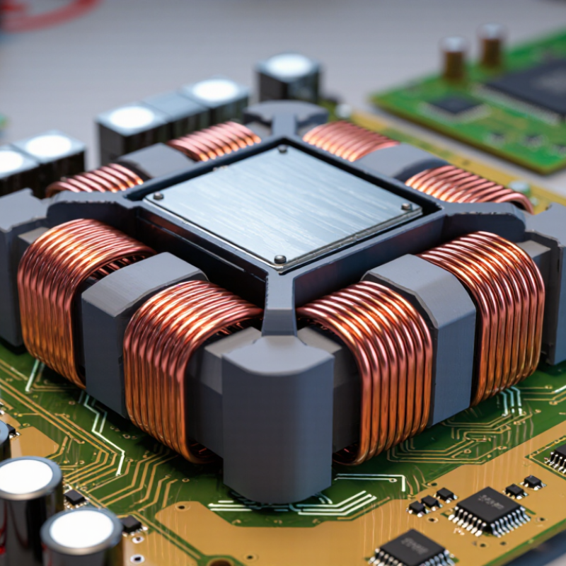
Power inductors store energy in a magnetic field and release it as current demand changes. Their internal structure is compact, but rarely simple. A typical part contains a copper winding, a magnetic core, insulation, terminals, and protective molding. The winding may sit around the core or inside it. Its geometry controls resistance, heat, and magnetic coupling.

Core material sets much of the component’s behavior. Ferrite offers low electrical loss at many switching frequencies. Powdered iron and other metal-powder materials can handle higher current before saturation. They also create more core loss and heat. Some designs use a distributed air gap, while others shape the gap inside the magnetic body. That tiny gap is easy to overlook. It stores energy and reduces abrupt saturation. A small manufacturing variation can still change inductance, so published values should not be treated as perfectly fixed.

Copper is common for the winding because it combines strong conductivity with practical mechanical strength. Thin enamel insulation prevents turn-to-turn shorts, while thicker barriers separate the winding from the core. Terminals may use plated conductive layers to improve solder joints and resist oxidation. Epoxy or molded compound protects the assembly from vibration and moisture. In bench testing, I would check temperature rise, direct-current resistance, and inductance under real load. A cool part at light load proves little. Mechanical stress can also produce noise, a detail that simplified datasheets sometimes underemphasize. The design is not perfectly tidy; heat, tolerance, and frequency often pull in different directions.

How Power Inductors Store and Release Energy

Power inductors store electrical energy inside a magnetic field created by current flowing through their windings. Their operation is simple, but the details matter. When current enters the coil, the inductor resists sudden changes. Energy builds around the magnetic core. The stored energy follows the relationship E = ½LI², where L is inductance and I is current. A 10 µH inductor carrying 2 A stores about 20 microjoules. That energy may seem small, yet it moves repeatedly through a power converter.

When a switching circuit changes state, the inductor releases energy into the load. Its magnetic field begins collapsing. The inductor then produces voltage that supports the existing current direction. This action helps create a steadier output from a pulsing input. On a circuit board, the process happens thousands or millions of times each second.

A useful warning: current does not stop instantly. Interrupting it carelessly can create a sharp voltage spike.

Real circuits are less tidy than diagrams. Wire resistance creates heat, while core losses reduce efficiency. Excessive current can push the core toward saturation. Inductance then falls, and ripple current may rise quickly. Engineers check temperature, peak current, switching frequency, and physical spacing before selecting a part.

I have found that calculated values often look reassuring until layout resistance and heat are measured. That gap deserves attention. A slightly imperfect model can still guide design, but it should never replace testing under real load.

Electrical Characteristics and Performance Ratings

What Are Power Inductors and How Do They Work?

Electrical Characteristics and Performance Ratings

A power inductor stores energy in a magnetic field while current flows through its winding. In a switching circuit, it releases that energy during each cycle. This action smooths current and helps regulate voltage. Inductance, measured in microhenries, describes how strongly the component resists changes in current. A higher value is not automatically better. It may reduce ripple, but it can also slow transient response.

On a test bench, I check inductance at the intended operating frequency and temperature. The reading can shift under real load. Direct-current resistance, or DCR, determines copper loss and heating. Lower DCR usually improves efficiency. Saturation current is equally important. Beyond this point, inductance drops sharply, and ripple current may rise. Watch this limit carefully. Rated current often means a specific temperature increase, such as 20 or 40 degrees Celsius. Those conditions matter.

Engineers should also review core loss, tolerance, insulation rating, and self-resonant frequency. Core loss grows with frequency and ripple amplitude, sometimes more than early calculations suggest. The self-resonant frequency marks where parasitic capacitance changes the component’s behavior. It is easy to trust one impressive number. That is a mistake. I have seen designs pass a bench test yet overheat inside a compact enclosure because airflow was ignored. A reliable selection compares every rating with the circuit’s actual waveform, duty cycle, ambient temperature, and fault conditions. Measurements remain essential, because datasheet values depend on test methods.

What Are Power Inductors and How Do They Work? - Electrical Characteristics and Performance Ratings

Electrical Characteristic What It Means Typical Range or Rating Why It Matters in a Circuit
Inductance The opposition to changes in current, determined by the magnetic field established around the winding. Approximately 0.1 µH to 1 mH for many power-conversion applications. Sets ripple current, energy-storage capability, transient response, and switching-converter operating conditions.
Inductance Tolerance The permitted deviation between the nominal inductance and the actual measured value. Commonly ±10%, ±20%, or ±30%. Affects current ripple, control-loop behavior, filter corner frequency, and production consistency.
DC Resistance (DCR) The winding resistance measured with direct current, excluding the inductive reactance. From less than 1 mΩ in high-current parts to several ohms in small, low-current parts. Determines copper conduction loss, voltage drop, efficiency, and part temperature rise.
Saturation Current (ISAT) The current at which the magnetic core begins to saturate and inductance decreases by a specified amount. Often specified at a 10%, 20%, or 30% inductance reduction; commonly ranges from below 1 A to more than 100 A. Must exceed the peak operating current to prevent excessive ripple, control instability, and overheating.
RMS Current Rating (IRMS) The continuous current that produces a specified temperature rise, usually based on winding losses. Commonly specified for a 20°C to 40°C temperature rise; actual current may range from hundreds of milliamps to tens of amps. Limits thermal stress caused by RMS current and helps maintain safe, reliable operation.
Rated Current A manufacturer-defined operating limit that may be based on temperature rise, saturation, or both. Must be interpreted together with the stated test conditions and derating requirements. Prevents designers from applying a single current value without considering thermal and magnetic limitations.
Self-Resonant Frequency (SRF) The frequency at which the inductive behavior is canceled by the component's parasitic capacitance. Typically from hundreds of kilohertz to hundreds of megahertz, depending on inductance, construction, and size. The inductor should generally operate well below its SRF when predictable inductive impedance is required.
Quality Factor (Q) The ratio of inductive reactance to effective loss at a specified frequency. Often approximately 10 to 100, depending strongly on frequency and construction. A higher Q generally indicates lower relative loss in filtering and resonant applications.
Core Material The magnetic material that concentrates and stores energy around the winding. Common materials include ferrite, powdered iron, metal composite, and air-core structures. Influences saturation behavior, core loss, electromagnetic interference, size, and usable frequency range.
Core Loss Energy dissipated in the magnetic core due to hysteresis and eddy-current effects. Increases with switching frequency, flux swing, and operating temperature; no universal fixed value applies. Contributes to total power loss and may limit frequency, efficiency, and thermal performance.
Temperature Rise The increase in component temperature above the surrounding ambient temperature. Common test specifications include 20°C, 30°C, or 40°C temperature rise. Determines whether the component can operate continuously without exceeding its thermal limit.
Operating Temperature The permitted ambient or component temperature range during operation. Common ranges include −40°C to +125°C or −40°C to +150°C, depending on construction. Supports reliable operation across environmental conditions and defines necessary current derating.
Energy Storage The energy stored in the magnetic field, calculated as E = ½LI². Depends on inductance and current; a 10 µH inductor carrying 5 A stores approximately 125 µJ. Explains the role of the inductor in buck, boost, buck-boost, and other energy-transfer converters.
Inductive Reactance The frequency-dependent opposition to alternating current, calculated as XL = 2πfL. For a 10 µH inductor at 100 kHz, XL is approximately 6.28 Ω before parasitic effects. Determines how effectively the component filters AC ripple at a particular frequency.
Shielding A construction feature that reduces magnetic flux leakage into nearby circuitry. Available as shielded, semi-shielded, or unshielded designs. Shielded designs are preferred where electromagnetic interference and board spacing are critical.
Package and Mounting The physical dimensions, terminal arrangement, and mounting method of the component. Common formats include surface-mount molded, wire-wound surface-mount, radial-leaded, and through-hole parts. Affects board area, heat dissipation, mechanical strength, current capability, and layout flexibility.

Note: Electrical ratings vary with test frequency, ambient temperature, waveform, measurement method, and allowable temperature rise. Always evaluate saturation current and RMS current under the actual application conditions.

Common Applications and Selection Considerations

Power inductors are magnetic components that store energy and smooth current in switching converters. Common applications include electric-vehicle inverters, battery chargers, servers, telecommunications equipment, and LED drivers.

In an EV power stage, the inductor converts a rapidly switched waveform into steadier current. That reduces ripple and protects sensitive circuits.

Demand is becoming harder to ignore. The IEA’s Global EV Outlook 2024 reports more than 14 million electric cars were sold worldwide in 2023. Each vehicle can contain several power-conversion stages.

Data-center power systems add another heavy load. The Uptime Institute’s Global Data Center Survey 2024 found that 45% of operators reported rising power constraints. These figures do not measure inductor demand directly, but they show why compact, efficient magnetic components matter.

Selection begins with inductance, saturation current, and RMS current. Check temperature rise at the real switching frequency, not only at room temperature. Low DC resistance improves efficiency, but smaller packages may heat faster.

Shielded construction can reduce interference near sensors and communication lines. Core material also affects losses at higher frequencies. A useful test compares efficiency, ripple, and temperature after thermal equilibrium.

Datasheets can look reassuring. Bench results may disagree. Layout matters too, and it is often underestimated. Leaving that variable untested remains a design weakness.