
News / Blog
7 Tips for Buying Electronic Capacitors
Electronic capacitors may look like small, interchangeable parts, but choosing one by appearance alone can create problems. A capacitor that fits the board may still have the wrong capacitance, voltage rating, or temperature range. In a power supply, ripple current and equivalent series resistance can affect heat and performance. In a timing or signal circuit, tolerance and dielectric behavior may matter more. The right choice depends on the circuit, operating conditions, and available space. Small details matter.
A careful purchase starts with the equipment’s requirements and the manufacturer’s datasheet. Check the part number, dimensions, lead spacing, polarity, and specified operating limits before ordering. Also consider expected service life, storage conditions, and whether the supplier provides traceable product information. These checks cannot guarantee a perfect result, but they reduce avoidable mismatches. A tempting low price is not always a real saving. I have seen how easy it is to focus on capacitance and miss a less obvious rating; that is a useful reminder to review the whole specification. These seven tips explain what to compare, which questions to ask, and when a capacitor may need expert review. They are intended as practical guidance, not a substitute for circuit analysis or the component maker’s recommendations. Start with the application, then verify each detail against reliable documentation.
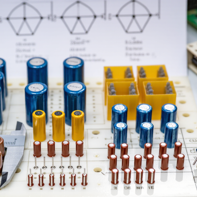
Identify the Circuit’s Capacitance and Tolerance Requirements
Capacitance and tolerance are circuit requirements, not interchangeable catalog details. Start with the circuit’s expected voltage, frequency, temperature range, and timing or filtering role. Then calculate the value it needs. A timing circuit using 10 kΩ and 100 nF has a nominal RC constant of 1 ms. If both parts are ±10%, the combined worst-case range is about 0.81–1.21 ms. That calculation is a useful design check, not a guarantee of real-world performance. IEC 60384-1:2021 sets common requirements and test methods for fixed capacitors; verify the specific part’s datasheet conditions before comparing tolerance figures.
Tip: Write down the allowed capacitance range, not just the nominal value. A ±10% capacitor marked 100 nF may measure from 90 to 110 nF under specified conditions. For ceramic parts, also check dielectric class: EIA-198 classification distinguishes temperature-stable Class I materials from Class II materials with greater capacitance variation. DC bias and aging can further reduce effective capacitance.
For a power-supply filter, a nominal value that looks adequate may fall short under operating voltage. Check the manufacturer’s capacitance-versus-bias and temperature curves, then allow margin where space and cost permit. I have seen designs focus on the printed tolerance and miss operating conditions. That is easy to overlook. Keep the reference conditions beside your calculation, and recheck the value in the assembled circuit.
7 Tips for Buying Electronic Capacitors - Identify the Circuit’s Capacitance and Tolerance Requirements
| Tip | Circuit example | Typical capacitance and tolerance | What to verify before buying |
|---|---|---|---|
| 1. Start with the circuit function | IC supply decoupling | 100 nF, commonly ±10% | Check the IC guidance, operating voltage, package size, and capacitor performance at the applied DC voltage. |
| 2. Calculate the required value | RC timing network | 10 nF, ±5% when tighter timing accuracy is needed | For a simple RC network, the time constant is τ = R × C. Include resistor tolerance and other circuit variations in the timing budget. |
| 3. Match tolerance to sensitivity | Precision filter or reference circuit | 10 nF, ±1% to ±5%, as required by the design | A tighter initial tolerance may improve accuracy, but also check temperature coefficient, aging, and operating conditions. |
| 4. Account for effective capacitance | Ceramic capacitor on a DC power rail | 1 µF, often specified at ±10% or ±20% | Class II ceramic capacitors can lose capacitance under DC bias; consult the part’s capacitance-versus-voltage data for the intended package and voltage. |
| 5. Check the full operating range | Temperature-sensitive oscillator or resonant circuit | 18 pF, commonly specified with a tight tolerance such as ±2% | Confirm the required dielectric temperature characteristics and include board and device parasitic capacitance in the circuit calculation. |
| 6. Allow for broad tolerance where appropriate | Bulk smoothing on a low-voltage DC rail | 470 µF, commonly ±20% for an aluminum electrolytic | Check minimum capacitance, ripple-current rating, ESR, temperature rating, lifetime, and polarity against the design requirements. |
| 7. Confirm application-specific requirements | Across-the-line mains interference suppression | 100 nF; tolerance depends on the specified circuit and part | Use a capacitor with the appropriate recognized safety class and AC rating for the circuit position; an ordinary DC-rated capacitor is not a substitute. |
Values and tolerances are illustrative examples, not universal design rules. Confirm the circuit specification and the selected capacitor’s datasheet before purchase.
Related Posts
-
10 Tips for Buying Electronic Capacitors?
-
Essential Tips for Choosing the Right Electronic Capacitors for Your Projects
-
Why Are Electronic Capacitors Important for Global Buyers?
-
Why Electronic Capacitors Are Essential for Modern Electronics
-

Top Capacitors vs Resistors: Key Differences and Applications Explained
-

2026 Top Trends in Electronic Capacitors for Future Innovations?